PiKVM V3 HAT & pre-assembled quickstart guide

PiKVM is a feature-rich, production-grade, open-source, Raspberry Pi based KVM-over-IP device. It allows you to turn your computer on or off, restart it, configure the UEFI/BIOS, and even reinstall the OS using the Virtual CD-ROM or flash drive.
PiKVM uses your remote keyboard and mouse to simulate a local keyboard, mouse, and monitor, which are then presented in a web browser as if you were working on a remote system directly.
PiKVM V3 is available in two version:
- An assembly kit (HAT).
- A pre-assembled unit in a metallic box.
The two versions have the same ports and functionality.
What's in the box
- The PiKVM V3 HAT for Raspberry Pi 4
- USB-C bridge board
- ATX adapter board with mounting brackets and motherboard interface wiring
- 2x Flat CSI-2 cables
- 7x jumpers
- 8x brass standoffs
- 8x screws
- PiKVM V3.3 pre-assembled
- ATX adapter board with mounting brackets and motherboard interface wiring
- A 32 GB MicroSD card pre-imaged with the PiKVM OS
HAT setup
If you have an assembly kit without a metal case, you can use our free 3D printing case drawing:
Once you have that, do the following:
-
Flash the memory card. Please use the V3 image, V2 image is not compatible.
-
Build PiKVM according to the illustrated instructions.
Interface

- 2x USB 2.0
- 2x USB 3.0
- RJ45 1Gb Ethernet port
- RJ45 Serial console port
- Serial console active LED / Beacon LED (Green)
- USB 2.0 Serial console port
- Activity LED (Red)
- Power LED (Green)
- Power Input 5.1V 3A

- Micro SD card slot
- HDMI video input port
- USB 2.0 OTG connector
- RJ45 ATX control port

- Mini-HDMI output port

- Display
Flashing the OS
Most of the time, this step is not necessary. However, if there is a possibility that your device had a previous owner (e.g. "Used - Like New" on Amazon), we recommend reflashing the OS to ensure a clean start. Please follow this guide.
Wiring
Both the HAT and the pre-assembled V3 require several items available separately:
- Ethernet cable
- RJ-45 cable for ATX (optional)
- USB-C cable
- HDMI cable
- 5V USB power adapter
Let's connect all the wires before you power up the device.
Network

Connect Ethernet (bottom right on the front side) to the network, e.g., to the WiFI router.
HDMI and USB-C

HDMI input (the top right on the rear side) and OTG port (USB emulation) should be connected to the computer.
Optionally, the ATX port can be connected to control the power. There should be no USB hub between PiKVM and the computer, as some UEFI/BIOS cannot detect them at the boot stage.
Power up

V3 comes has a USB-C 5V power supply. Attach the appropriate connector on the front side (top left). Do not block the ventilation holes on the sides of the device.
After turning on the power, PiKVM OS generates unique SSH keys and certificates and performs all necessary operations on the memory card. It takes a few minutes. Do not turn off the device until it's fully booted for the first time. Once it's done, the PiKVM will show a greeting on the built-in display.
Connect and set up
Configure the display
The operating system on your remote computer will treat PiKVM as an additional display and use it in the Extend mode by default. That's why you will see an empty desktop when you first connect.
To avoid that, go to the display settings in your remote computer's operating system and enable the mirror mode for the external screen that you operating system identifies as PiKVM. Refer to your operating system's documentation on that.
Access PiKVM
By default, PiKVM receives a dynamic IP address via DHCP and shows it in the top row of the OLED display:
192.168.0.26
(|) iface: eth0
cpu: 1% mem: 13%
Let's assume that PiKVM has received the address 192.168.0.26 and has also been assigned a hostname pikvm.
Type the URL in the browser's address bar and press Enter: https://192.168.0.26/ or https://pikvm/.
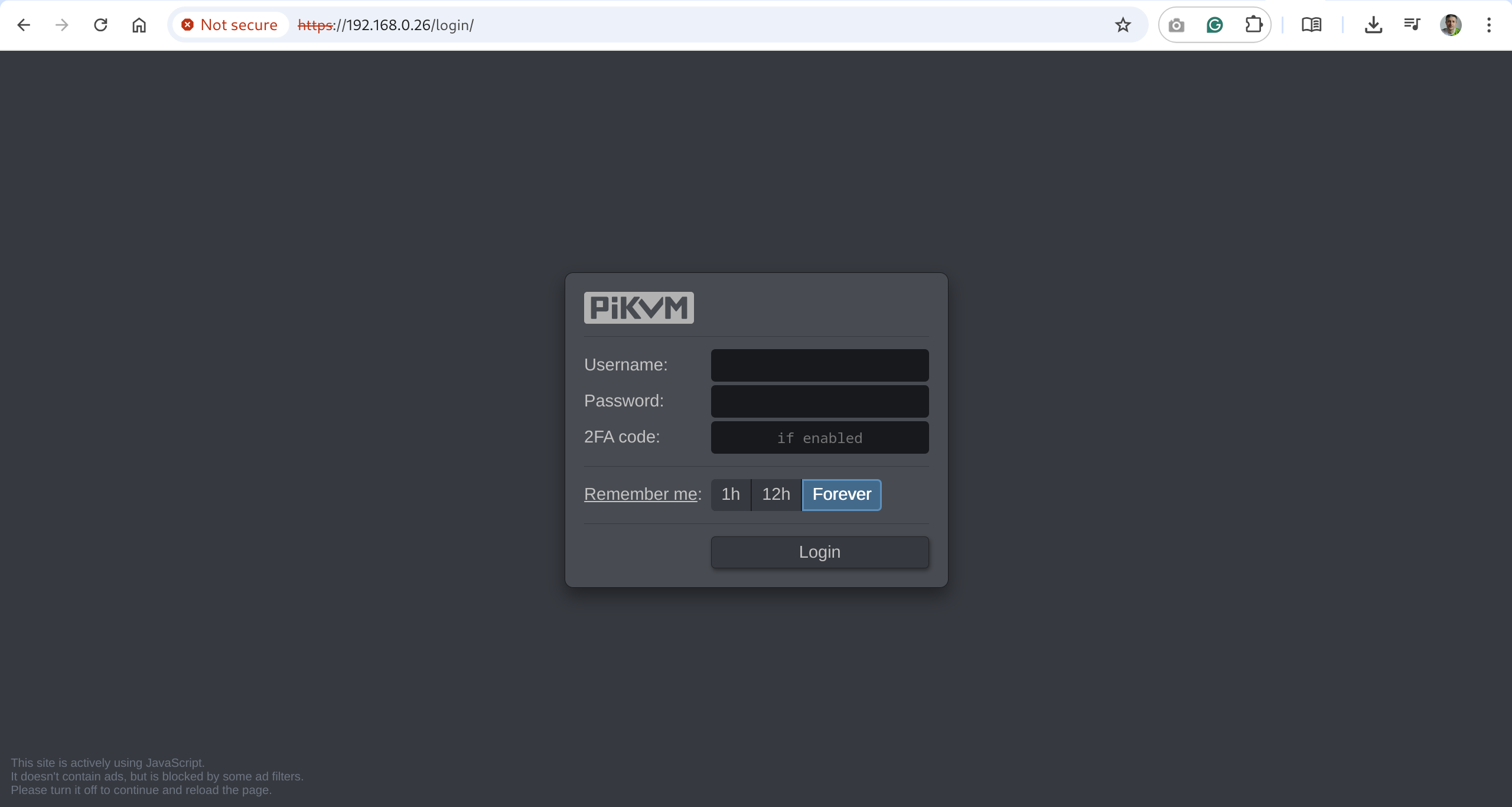
Submit the default credentials and click Login:
- Username:
admin - Password:
admin - 2FA Code: disabled by default, skip this field
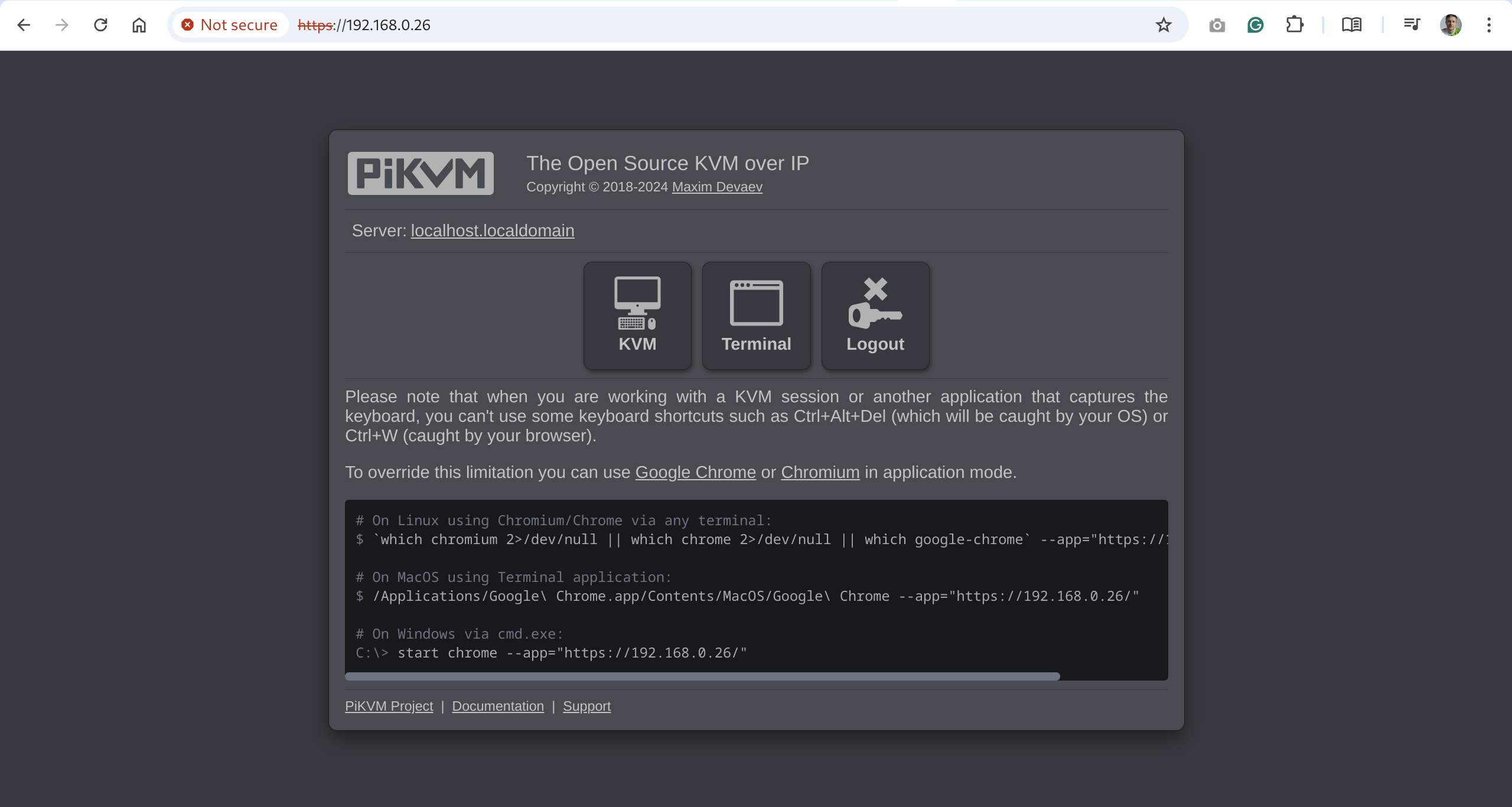
You will see the initial dashboard screen of the PiKVM where you can access the remote host, connect to the PiKVM command line, or log out:
Change the default passwords
For security's sake, it's best to change the default passwords immediately after running PiKVM for the first time.
Passwords are important!
Please ensure that you change both passwords: for Web UI access and for the Linux superuser (root).
To do that:
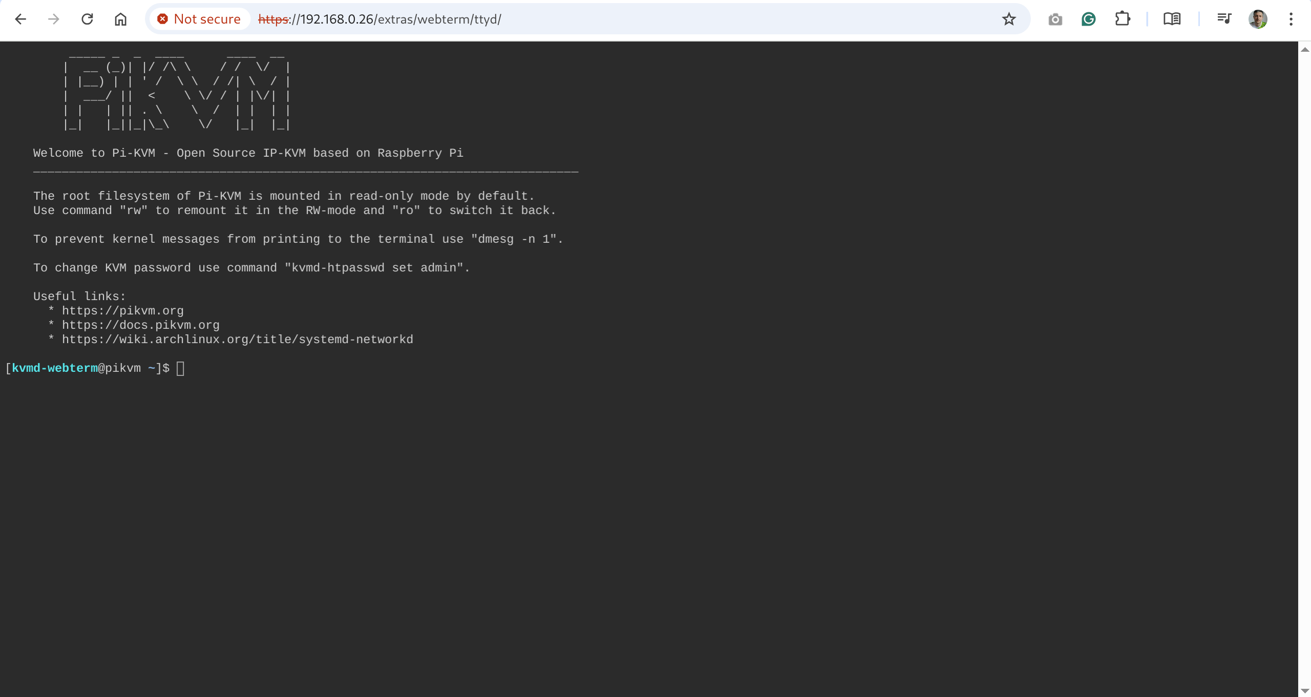
-
On the initial dashboard screen, click the Terminal button to open the web terminal. You will see this command line interface:
-
Gain Linux superuser privileges:
$ su -When prompted for password, use
root. -
Run
rwto change the access to the SD card to the write mode:[root@pikvm ~]# rw -
Change the password for the Linux superuser:
[root@pikvm ~]# passwd rootSubmit the new password, retype it the second time to confirm, press Enter, and you should see this:
passwd: password updated successfully -
Change the password for web access:
[root@pikvm ~]# kvmd-htpasswd set adminSubmit the new password, retype it the second time to confirm, and press Enter.
-
Run
roto change the access to the SD card back to the read-only mode:[root@pikvm ~]# ro -
Press Ctrl+D or type "exit" and press Enter to drop the root privileges.
-
Go back one page in the browser. You should be back to the initial dashboard screen.
Access the remote system
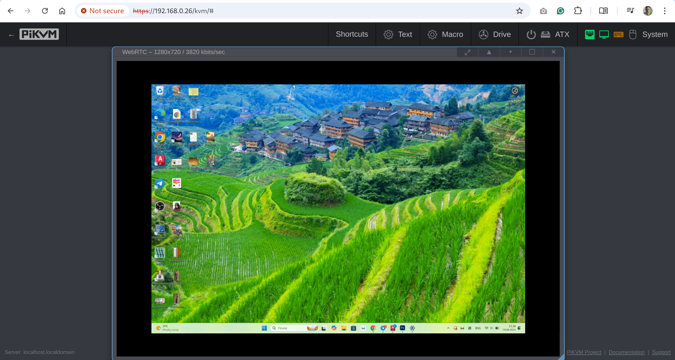
-
On the initial dashboard screen, click the KVM button to access the remote host.
-
You should now see the host system's display and interact with it remotely using a keyboard and a mouse.
Important next steps
-
We strongly recommend to update the PiKVM OS after the first launch:
Updating PiKVM OS
Tip
We recommend updating PiKVM OS only if you have physical access to the device, or in the most extreme cases. The update process is very reliable, but there is always a small chance that something may go wrong so reflashing will be required. PiKVM cannot be bricked, but you need physical access to the memory card for this operation.
To update, run following commands under the
rootuser:[root@pikvm ~]# pikvm-updateIf you encounter an error like:
[root@pikvm ~]# pikvm-update
bash: pikvm-update: command not found
It's most likely you have an old OS release. You can update the OS as follows:
[root@pikvm ~]# rw
[root@pikvm ~]# pacman -Syy
[root@pikvm ~]# pacman -S pikvm-os-updater
[root@pikvm ~]# pikvm-update
Next time you will be able to use the usual method with
pikvm-update. -
Learn about basics of PiKVM OS Configuration: where to find configs, how to edit the, etc.
Configuring PiKVM OS
Need more info? We have it!
The following is a brief guide to configuring PiKVM. For more information (including the basics of YAML syntax and how to use a text editor in the Linux console), please refer to this page.
Most of the PiKVM configuration files are located in the
/etc/kvmddirectory.The
/usr/lib/kvmd/main.yamlfile defines the platform configuration, and you should never edit it. To redefine system parameters use the file/etc/kvmd/override.yaml. All other files that are also not recommended for editing have read-only permissions.For automated deployment, you can put
.*yamlfiles into/etc/kvmd/override.ddirectory. Theoverride.yamlfile definitions takes precedence over theoverride.ddirectory and it is intended for local manual configuration.A complete list of all parameters can be viewed using the
kvmd -mcommand.A list of your non-default overrides can be viewed using the
kvmd -Mcommand.Files with the
*.yamlsuffix uses the YAML syntax and describes a parameter tree with key-value pairs of different types. To define the parameters within one section, an indent of 4 spaces is used. Comments starts with the#symbol.Only 4 spaces should be used for indentation
Be careful when editing YAML and follow this rule. Invalid indentation or tabs instead of spaces will cause an error when starting the services.
Sections under the same keys should be merged:
-
Wrong:
kvmd: gpio: drivers: ... kvmd: gpio: scheme: ... -
Correct:
kvmd:
    gpio:
        drivers: ...
        scheme: ...
For simple config overrides you don't need to use a text editor, you can do this with
kvmd-overridecommand. For example, enabling the microphone audio on PiKVM V3/V4:[root@pikvm ~]# kvmd-override --set otg/devices/audio/enabled=trueThis puts a config override looks like this:
otg:
    devices:
        audio:
            enabled: true
In the
/etc/kvmd/meta.yamlfile you can specify some information regarding this PiKVM installation in an almost free YAML format. -
-
Get to know PiKVM Web UI: read this help section to better understand all the possibilities of the web user interface.
-
Configure the magic key: define which key to use to start sending shortcuts to the target host system.
-
Set up ATX connection if you need to control the power of the remote system.
Further recommendations
-
Customize the system:
- Harden the remote access by enabling 2FA.
- Configure access to PiKVM from the Internet using port forwarding or Tailscale VPN.
- Enable a microphone for two-way audio.
- Learn how configuration files are structured.
- Read how PiKVM is identified on the target host.
-
Configure hardware:
-
If you bought V3 HAT Assembly Kit and it includes the OLED display and/or the fan, you'll need to turn them on. Note this is only needed for the older V3 image for the HAT, in the box image everything is enabled by default:
Enabling the OLED and the fan
Log in to PiKVM and run these commands:
[root@pikvm ~]# rw [root@pikvm ~]# systemctl enable --now kvmd-oled kvmd-oled-reboot kvmd-oled-shutdown [root@pikvm ~]# systemctl enable --now kvmd-fan [root@pikvm ~]# ro -
Choose Fahrenheit over Celsius to display on the OLED:
How to set up Fahrenheit on the OLED
Create a directory for a configuration file:
[root@pikvm ~]# mkdir -p /etc/systemd/system/kvmd-oled.service.dCreate file
/etc/systemd/system/kvmd-oled.service.d/override.conf:[Service] ExecStart= ExecStart=/usr/bin/kvmd-oled --clear-on-exit --fahrenheit
-
Known issues and limitations
-
Max resolution.
PiKVM V3 supports maximum resolution 1920x1080@50Hz, 60Hz will not work. You can use any other resolution less than the specified one, for example: 1600x1200@60Hz, 1280x720@60Hz, etc. If you have problems with the video, follow this guide. -
Motherboards compatibility.
There may be compatibility issues with some motherboards, such as HP or DELL. If there is no image from the BIOS, you can fine-tune the HDMI settings, but it is possible that the mass storage devices will not be available in the BIOS. In the latter case, USB dynamic configuration will solve the problem. -
HDMI backpowering.
Under specific circumstances, PiKVM may hang during the boot. Turn off the PiKVM, disconnect all cables from it, take a close look at the diagram of its ports and jumpers below, and remove jumper #14 (it is to the right of the CSI connector, not available on the V3.2 board). Then you can connect and power up PiKVM again. (Technical background s described here.) -
IO ports.
Before using GPIO pins to control a relay, KVM switch, or anything else, be sure to check the HAT pinout below. Many ports are busy with internal functions. Before using them for your own use, you must disable them, otherwise you may damage the PiKVM WebTerm
The ports and jumpers diagram
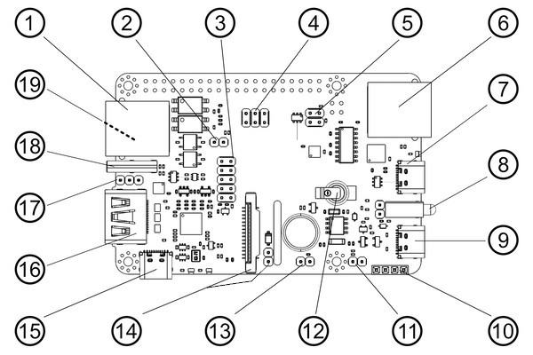
- ATX controller interface (power on/off, reboot control, PWR and HDD ACT LEDs).
- HDMI reset jumper. Connects GPIO 17 and RESET pin to HDMI capture chip. Currently not used, don't touch it.
- SPI and GPIO for the custom extension boards.
- Audio capture jumpers. Connects I2S pins 18, 19, 20 to HDMI capture chip.
- UART access jumpers. Connects GPIO 14 and 15 to the RJ-45 and USB console ports.
- Serial console port (default: /dev/ttyAMA0, RS232 input, outputs +6V/-6V, for the Raspberry Pi or server console access, use the Cisco/Mikrotik-style cable).
- USB-C console port (shared with #6 above, takes priority over RJ45).
- Power and activity LEDs. On the left of the LEDs the watchdog jumper is located. Don't touch it.
- USB-C power input.
- I2C display connector.
- Alternate +5V power input/output header pins.
- RTC clock supercapacitor (rechargeable).
- FAN connector - PWM controlled.
- CSI-2 interface and HDMI backpowering jumper, see Step 9 of the Basic Setup. Open: (jumper removed) diode will stop current from HDMI input (backpower will be fixed), closed: (jumper connected to both pins) will allow current from HDMI device.
- Built-in power splitter port.
- HDMI capture port (max 1080p @ 50Hz) with sound capture support.
- USB emulation pins for alternative access.
- USB-C emulation port - this port is doing the emulation of a USB keyboard, mouse, Virtual CD-ROM or USB Flash Drive, USB-Ethernet, USB-Serial port and a lot of other Linux-supported features.
- 1-Wire & Neo-pixel interface (under, advanced user feature).
The GPIO pinout
Warning
Before proceeding, make sure that the mb you are using has normal ATX headers
- ATX control
power led = GPIO 24- Used for reading the host power state.hdd led = 22- Same for the HDD activity.power switch = 23- Used for pressing the power button of the host.reset switch = 27- Same for the reset button.
These pins can't be used for any other purposes even if ATX function is disabled.
-
I2C bus -
GPIO 2, 3- Can be used as I2C ONLY (OLED/RTC). -
1-Wire [19] -
GPIO 4- Also available under ATX RJ-45 port (point [19] on the above) as bi-directional buffered open-drain 5V for regular 1-Wire usage. -
UART -
GPIO 14, 15- Can be used as UART only for the serial console. When jumpers [5] are removed, you can connect to pins 14 and 15 directly using GPIO header. Also you can remove jumper [5] and disable UART console in the/boot/config.txtand/boot/cmdline.txtto use this pins for any purpose. But it's not recommended. -
Red activity led on the front [8] -
GPIO 13- Can be disabled in/boot/config.txtand available on the Neo-pixel port [19]. -
PWM fan controller -
GPIO 12. Can be used for custom purposes if the fan disconnected andkvmd-fanservice is stopped. -
I2S HDMI sound -
GPIO 18, 19, 20, 21. Can be used for custom purposes if thetc358743-audiooverlay in/boot/config.txtis disabled AND jumpers [4] are removed. -
USB breaker -
GPIO 5- Can't be used for any other purposes.
The standard Raspberry Pi HDMI output (marked as VIDEO OUT on the PiKVM case) displays its own PiKVM OS console.
Basic troubleshooting
-
Ensure that you are using the right OS image for your platform by running the following command:
pacman -Q | grep kvmd-platform. -
If you are not getting a display, run the two following commands:
dmesg | egrep 'tc35|1-1.4|uvc'systemctl status kvmd-tc358743
Getting user support
If something doesn't work, check out our FAQ. Otherwise, head straight to our Support.