ATX board
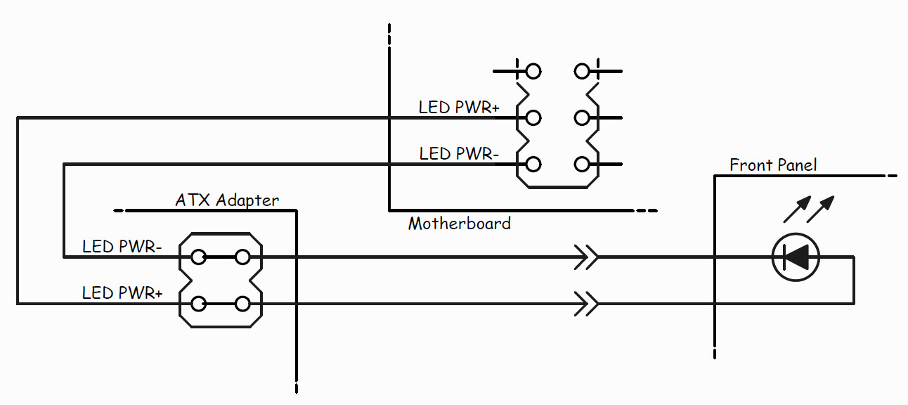
To manage the power of your computer, you will need to install an ATX adapter board inside the case and connect it to the motherboard. There is a female to female ribbon cable that goes from the motherboard to the ATX adapter board and a male to female ribbon cable that goes from the adapter board to the front panel ribbon cable. There are two rows of pins on the ATX adapter board, it does not matter which ribbon cable is attached to which row. The columns must line up from the front panel through the ATX adapter to the motherboard.
Apple's Mac computers are not ATX compatible as they lack the needed ATX headers, this is ONLY compatible with PC servers and desktops.
Detailed instructions
-
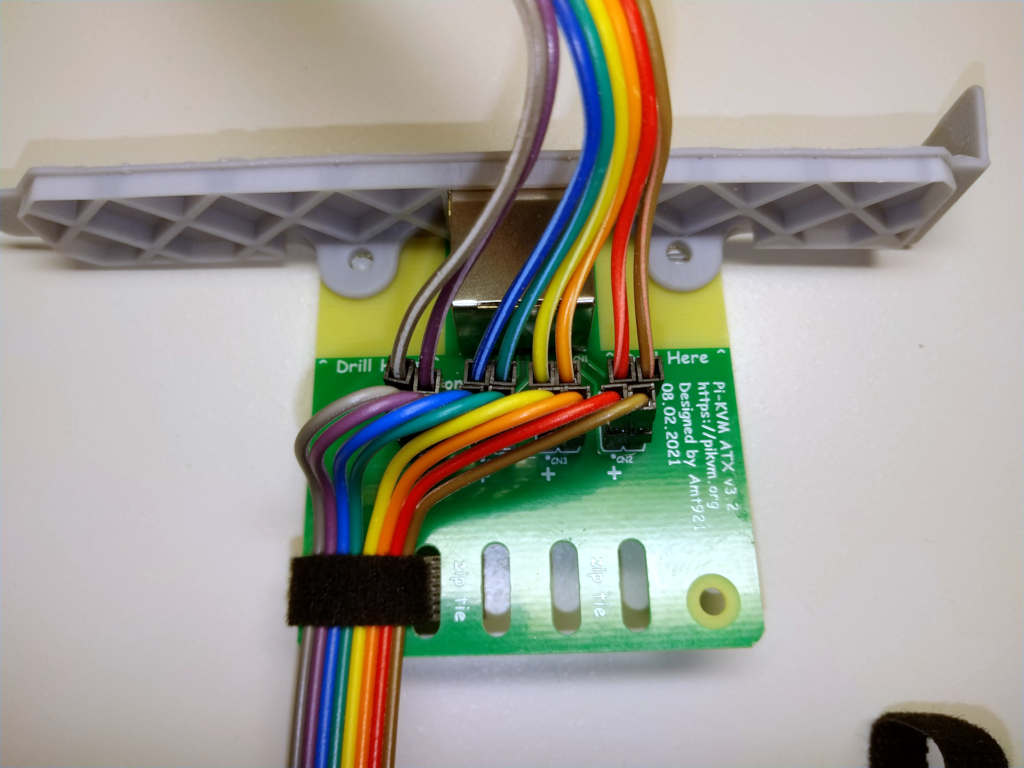
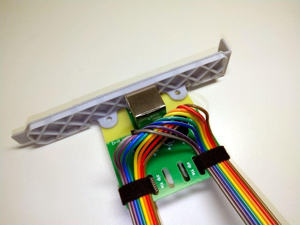
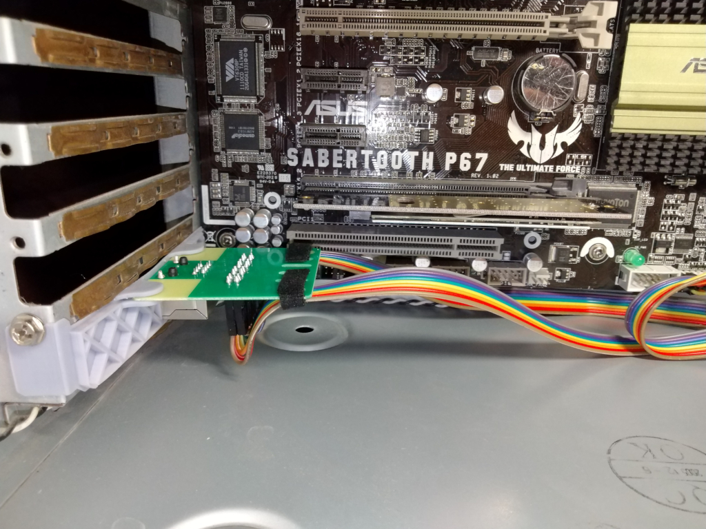
Connect the rainbow wires to the board, one row to the front panel, one row to the motherboard. You can use either row for either cable. To secure the ATX board in the case you can optionally print the mounting plate for the PCI slot on a 3D-printer. Assemble everything like the pictures below. Secure wires in any convenient way (we used soft ties).
Example
-
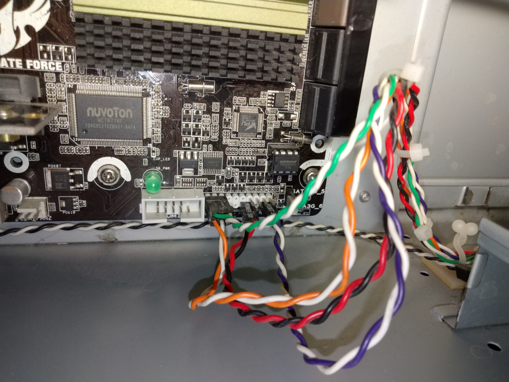
Find the pins on the motherboard responsible for connecting the buttons and LEDs of the front panel of the case. Usually wires and connectors on the motherboard have designations. If you're not sure, check the documentation on your motherboard.
Example
-
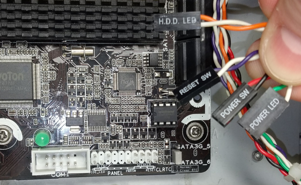
Place the ATX board nearby and, focusing on the labels and polarity (+ or -), connect the male pins to the female pin of the front panel wires. Be sure to align the labels and polarity (the polarity is indicated on the ATX board).
Example
-
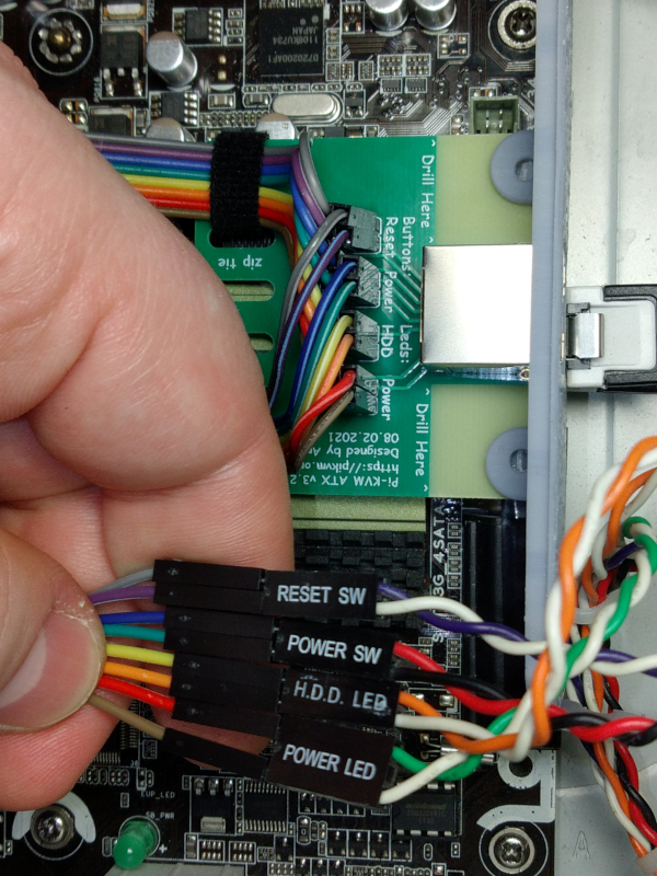
Repeat the procedure with the female pin of the ATX board by connecting them to the motherboard connector. Check the documentation on your motherboard to find out which pin on the motherboard goes to which pin on the ATX adapter. Sometimes it is printed on the motherboard.
Example
-
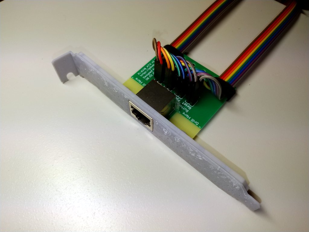
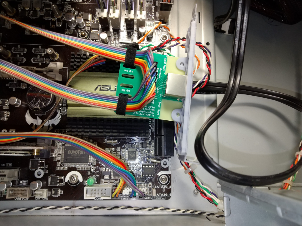
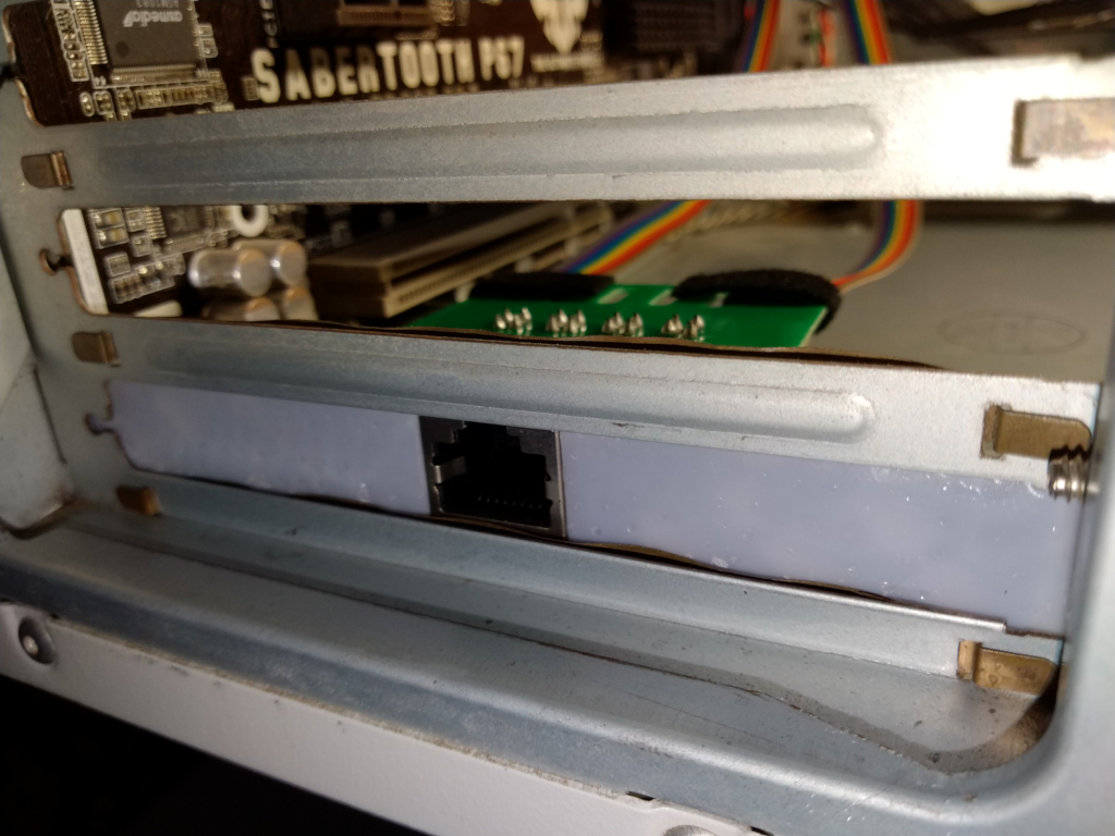
Install the ATX board into the PCI slot of the case and fix it with a screw, or use a different mounting method at your discretion.
Example
-
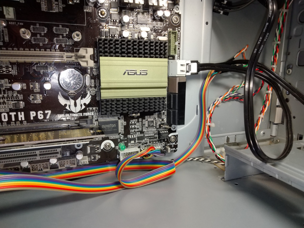
Arrange the wires in a way that is convenient for you and fix them if necessary. Ensure the cables do not come into contact with any fans in your case.
Example
-
Connect the ATX board to PiKVM using a straight Ethernet cable with 8 wires.
Example
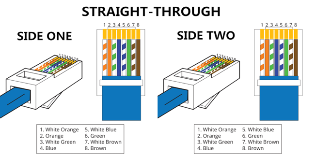
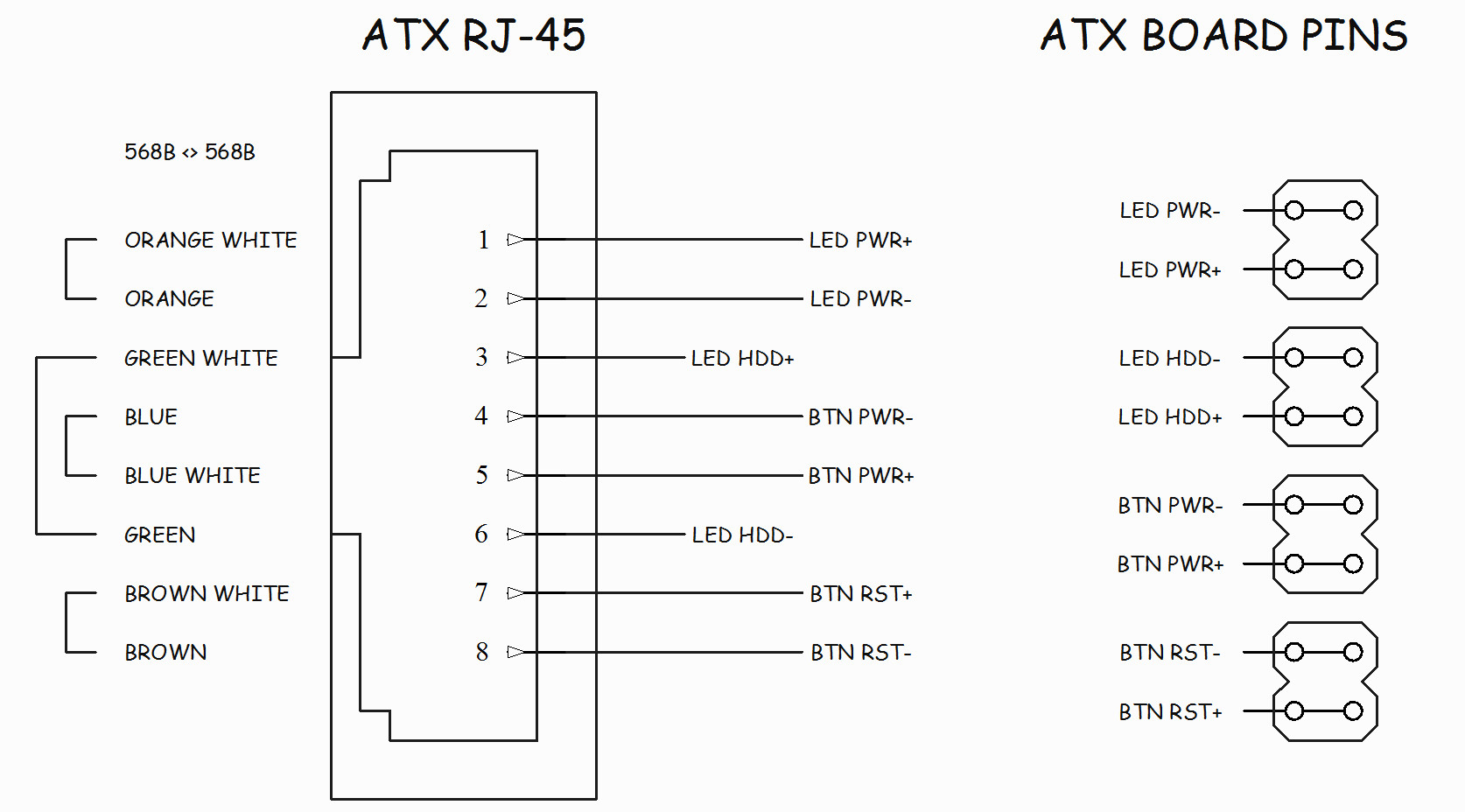
Pinout
ATX RJ-45 pinout
The pinout of the RJ-45 connector is the same on the AT and ATX adapter.
ATX LED wiring example