XH-HK4401 4-port HDMI USB KVM Switch
This document was supplied by a community member, thus it is not officially endorsed or supported.
PiKVM + Multiport Switches compatibility
Please note that this switch requires a USB port for control. The following devices can provide this:
- PiKVM V3 & V4 Plus.
- DIY devices based on Raspberry Pi 2, 3 and 4.
The following devices are not compatible:
- PiKVM V4 Mini - it doesn't have a USB host port and cannot control switches, it's a single-host device.
- DIY based on Raspberry Pi Zero 2 W - it doesn't have USB host port too.

This KVM is sold under many names, and comes in two versions. The only way these two versions differ is that one has one of its USB ports replaced with a PS/2 port. The identifying feature is that they come with a small external control unit with 4 buttons. This controller is connected to the main KVM via a micro USB cable, however this is NOT as USB connection.
Warning
Audio was not tested, it is assumed to be non-functional
Connections
-
Connect the USB-A cable from the Raspberry Pi OTG port to to any of the USB ports on the XH-HK4401 switch. All 3/4 USB ports work exactly the same, internally they are just connected to a USB HUB.
-
Connect the HDMI out from the XH-HK4401 switch to the Raspberry Pi CSI-2 to HDMI input.
-
Connect host USB and HDMI cables from the XH-HK4401 switch to the machines to be managed per the switch instructions.
-
Finally see below for details about connecting to the control micro USB port. This it not a normal USB micro port.
Warning
There is a limitation in the underlying PiKVM software related to plugging video cables from a host which is already powered and connected to a monitor to a Raspberry Pi HDMI-CSI bridge. These limitations apply equally when using the XH-HK4401 KVM switch. If video is not present in PiKVM, try keeping all host machines off and connecting them directly to the XH-HK4401 switch before powering the hosts on.
RS-232 control cable
The control unit communicates to the KVM using the RS-232 protocol (at 5v) not USB, and one of the following solutions must be used.
Inverting USB UART adapter (FT-232) - The easy way
Some USB UART adapters have the rare feature to invert the logic level of the RX/TX signals. For example the FTDI FT232 can be configured via the FTDI configuration GUI to do this. With such an adapter, the circuit above is not required. All you need is to connect it to a micro-USB connector.
Warning
These options will only work on UART adapters with genuine FTDI chips. There are a lot of cheap fakes on the market that either lack this option, or will prevent you from changing the settings. To avoid getting a fake ensure you always purchase from a reputable store and brand (Adafruit, Sparkfun, etc.), Amazon is not a reputable store.
Linux Instructions
References I used to get my FTDIs working:
- https://waterpigs.co.uk/articles/ftdi-configure-mac-linux/
- https://manpages.debian.org/testing/ftdi-eeprom/ftdi_eeprom.1.en.html
- https://manpages.ubuntu.com/manpages/bionic/man1/ftdi_eeprom.1.html
- http://developer.intra2net.com/git/?p=libftdi;a=blob;f=src/ftdi.h
- http://developer.intra2net.com/git/?p=libftdi;a=blob;f=src/ftdi.c
- http://developer.intra2net.com/git/?p=libftdi;a=tree;f=ftdi_eeprom
- http://developer.intra2net.com/git/?p=libftdi;a=blob;f=ftdi_eeprom/example.conf
- http://developer.intra2net.com/git/?p=libftdi;a=blob;f=ftdi_eeprom/main.c
Warning
Steps were performed on Debian-like installation (Pop!_OS 21.10)
This workflow has worked for a self-described NON-genuine FTDI FT232RL chip. The other MAY be genuine, but it is also working.
Neither of the following FTDI UART adapters are recommended. Purchasing both chips was an error (only 1 intended). However, having two (potentially non-genuine) FTDI UART adapters helped to create these instructions.
Warning
The HiLetGo UART adapter comes with a USB MINI female connector and necessitates another adapter/cable for interfacing with the Pi.
-
Get info from FTDI
- Plug the FTDI into a USB port on your Linux device and run
lsusbto verify that the device is foundlsusb - Ensure the device is recognized as FTDI
sudo lshw | grep -B 10 ftdi - Record hardware information (not sure if needed, but was saved to prevent overwriting critical data in the EEPROM)
- Plug the FTDI into a USB port on your Linux device and run
-
Blacklist ftdi_sio kernel module
- The kernel module ==ftdi_sio== is currently enabled (and how you saw the device in the previous step). We need to disable this module to read/write to the EEPROM.
- The following command creates a file to blacklist the ==ftdi_sio== module.
echo "blacklist ftdi_sio" | sudo tee /etc/modprobe.d/bl-ftdi.conf > /dev/null
-
Reboot machine
- We need to reboot into an environment without ftdi_sio active.
shutdown -r 0
- We need to reboot into an environment without ftdi_sio active.
-
Install ftdi_eeprom if not already installed
- Install ==ftdi_eeprom== with the following command.
sudo apt install ftdi_eeprom
- Install ==ftdi_eeprom== with the following command.
-
Make a folder to work from and change it to our working directory
mkdir ./ftdi_config cd ./ftdi_config -
Create a valid FTDI configuration file for ftdi_eeprom consumption
- The below command (copy/paste all lines) will create a valid configuration file. Change parameters as required.
tee ./ftdi.conf > /dev/null <<EOF filename=eeprom.bin vendor_id=0x0403 product_id=0x6001 manufacturer="FTDI" product="FT232 Serial (UART)" serial="SERIAL" use_serial=true max_power=500 self_powered=false invert_txd=true invert_rxd=true cha_type="UART" EOF - This configuration is trimmed from the example due to size of the EEPROM on the FTDIs used.
- The example configuration at ==/usr/share/doc/ftdi-eeprom/example.conf== describes possible configuration options for the FTDI and is well-documented.
- The above configuration worked for the mentioned devices. The ==filename==, ==vendor_id==, ==product_id==, ==invert_txd==, and ==invert_rxd== variables are required. The others might not be, but seemed applicable.
- If you're using a different FTDI chip than used here, please update that in the above configuration. Ensure that vendor_id and product_id are what was obtained from the output of the initial
lsusbcommand. - ==max_power==, ==serial==, and ==product== were updated to reflect the output of the initial
lshw. These updates may not be required and were done to avoid overwriting anything important. ==cha_type== was updated to ==UART== where both of the devices were originally designated as FIFO.
- The below command (copy/paste all lines) will create a valid configuration file. Change parameters as required.
-
Test the configuration and read the eeprom initially before flashing
- Read the EEPROM with the following command
sudo ftdi_eeprom --read-eeprom ./ftdi.conf - If you get an error here, there's something wrong with your configuration. Check that the device is properly identified and try again.
- Read the EEPROM with the following command
-
Rename/preserve and review the contents of the binary read from the EEPROM
- First, rename the output binary file so we don't overwrite it when we flash (flashing writes the flashed binary to the ==filename== path)
mv ./eeprom.bin ./original_eeprom.bin - Then, display the outputs of the binary
hexdump -C original_eeprom.bin - You can rename the binary in the configuration file by editing the ==filename== variable. If you can't be bothered to edit the file, rename it as detailed above.
- First, rename the output binary file so we don't overwrite it when we flash (flashing writes the flashed binary to the ==filename== path)
-
Flash the configuration
- Run the following command to flash the EEPROM of the FTDI
sudo ftdi_eeprom --flash-eeprom ./ftdi.conf - Optional: compare the flashed configuration to the initial configuration with the below command. If there is no output, the files are the same. You will likely need to re-flash.
diff <(xxd original_eeprom.bin) <(xxd eeprom.bin) - Alternatively, you can manually compare the files by running
hexdump -C original_eeprom.binandhexdump -C eeprom.bin
- Run the following command to flash the EEPROM of the FTDI
-
Your FTDI should be flashed and working to control the KVM!
- Plug it into one of the Pi's USB slots (if not already), and it's good to go.
- The KVM will sink power from the FTDI (Pi) if Vcc is connected. If Vcc is disconnected, ensure that grounds between the Pi and KVM are tied.
-
Clean up the ftdi blacklist to reenable the ftdi_sio module
- Comment out the line but leave the file with the following command:
sudo sed -i 's/blacklist ftdi_sio/#blacklist ftdi_sio/g' /etc/modprobe.d/bl-ftdi.conf - If you'd need to read/flash FTDI EEPROM in the future, you can use the following command (followed by a reboot) to blacklist the ==ftdi_sio== module again.
sudo sed -i 's/#blacklist ftdi_sio/blacklist ftdi_sio/g' /etc/modprobe.d/bl-ftdi.conf - If you want to wash your hands of FTDI flashing, then delete the blacklist file with the following command:
sudo rm /etc/modprobe.d/bl-ftdi.conf
- Comment out the line but leave the file with the following command:
-
Reboot the machine to reset to initial state (with ftdi_sio loaded)
- ==ftdi_sio== should reload as the driver, and the FTDI should be able to be seen with
lshw/dmesgonce again. If you tried to run either command while ==ftdi_sio== was blacklisted, you probably would have come up empty.
- ==ftdi_sio== should reload as the driver, and the FTDI should be able to be seen with
Windows Instructions
In order to invert the RX/TX signals, you can use ft_prog and set the following settings:
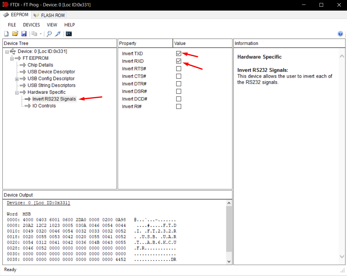
Once the UART is configured, please fully disconnect it and connect it back to the computer. Relaunch ft_prog and ensure the settings are still set. If they are not, you have a fake FTDI chip.
FTDI Terminal Configuration
Finally, you will need to connect it to the micro USB port (This it not a normal USB micro port.) like so:
| Signal | Colour | FT232 Pin |
|---|---|---|
| Vbus | Red | 5v (if you want to power the KVM from the Pi's USB) |
| D- | White | RX |
| D+ | Green | TX |
| Gnd | Black | GND |
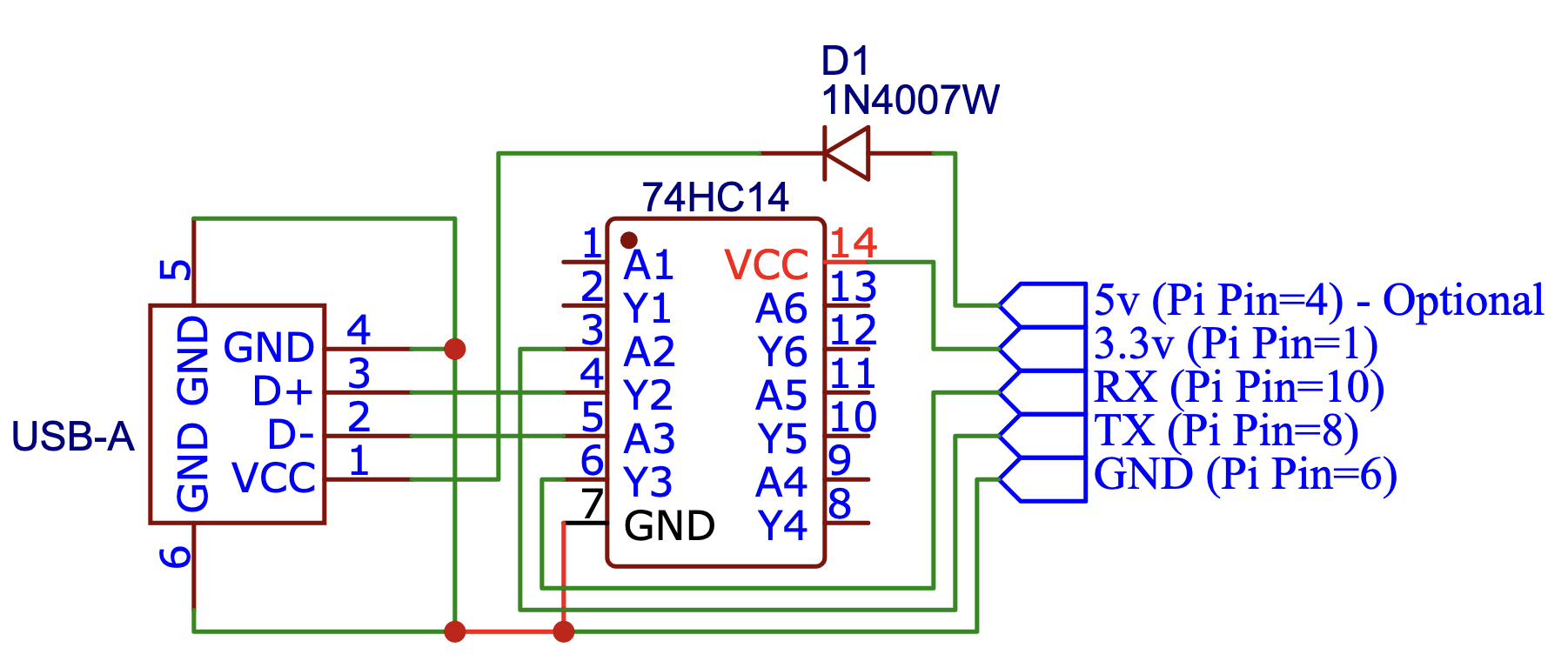
An inverter circuit - The cheap way
For this you will need:
- 1x 74HC14
- 1x USB A socket, or sacrificial micro USB cable
- Optional 1x Diode - If you want to power the KVM from the Raspberry Pi
- 1x 5-pin header
- 5x Female - Female jumper cables
Note
Please search online for USB pinouts to ensure you connect it properly.
Adding UI elements to control the KVM switch
The UI can be updated to add buttons to switch between KVM inputs and indicators for which input is currently selected. The instructions below will make these available in the PiKVM UI after clicking the "GPIO" menu button in the KVM view.
-
SSH into PiKVM
-
Enable read-write mode on the sd card via
rw -
Edit the
/etc/kvmd/override.yamlfile and include the following.
| Method | Device |
|---|---|
| FT-232 | /dev/ttyUSB0 |
| Inverter | /dev/ttyAMA0 |
kvmd:
    gpio:
        drivers:
            hk:
                type: xh_hk4401
                device: /dev/ttyUSB0
        scheme:
            ch0_led:
                driver: hk
                pin: 0
                mode: input
            ch1_led:
                driver: hk
                pin: 1
                mode: input
            ch2_led:
                driver: hk
                pin: 2
                mode: input
            ch3_led:
                driver: hk
                pin: 3
                mode: input
            ch0_button:
                driver: hk
                pin: 0
                mode: output
                switch: false
            ch1_button:
                driver: hk
                pin: 1
                mode: output
                switch: false
            ch2_button:
                driver: hk
                pin: 2
                mode: output
                switch: false
            ch3_button:
                driver: hk
                pin: 3
                mode: output
                switch: false
        view:
            table:
                - ["#Input 1", ch0_led, ch0_button]
                - ["#Input 2", ch1_led, ch1_button]
                - ["#Input 3", ch2_led, ch2_button]
                - ["#Input 4", ch3_led, ch3_button]
-
Return to read-only mode for the sd card via
ro -
Restart the kvmd service:
systemctl restart kvmd
Switching between hosts in the UI
To switch between hosts, enter the KVM UI and click the "GPIO" menu. You should see 4 inputs, one of which will have a green circle indicating it is currently selected. Click the other inputs to change the selected host.
Please review this latest issue for an update to the existing instructions