DIY PiKVM V2 quickstart guide
So many choices!
There are many different options with sub-items, so you can choose what will suit you.
However, we marked the recommended way by sign ✮ ✮ ✮
Required parts
-
MicroSD card minimum 16Gb class 10.
-
Raspberry Pi board:
- ✮ ✮ ✮ Raspberry Pi 4 2Gb.
It makes no sense to buy a Pi 4 with more memory than 2Gb, since PiKVM software uses very few resources. - ... or Raspberry Pi Zero 2 W.
Compact and cheap, but not so reliable solution because of lack of the wired Ethernet. - ... Raspberry Pi 5 is not supported right now. It doesn't have GPU video encoders, therefore, there is no point in using it for PiKVM, it will not give any performance boost for this case. The Pi 5 is a great device, just not suitable for PiKVM.
- ✮ ✮ ✮ Raspberry Pi 4 2Gb.
-
Video capture device:
- ✮ ✮ ✮ HDMI-CSI bridge based on TC358743 chip.
Supports H.264 video encoding, automatic resolution selection and the lowest possible latency. - ... or HDMI-USB dongle (not available for Pi Zero 2).
Only heavy MJPEG video, no resolution detection, big latency compared to HDMI-CSI. Some users report hardware problems: the dongle may not work in the BIOS or simply stop working after a while. It's a black box, and no one knows what's inside it. If you have problems with it, it will not be possible to fix them.
- ✮ ✮ ✮ HDMI-CSI bridge based on TC358743 chip.
-
Board-specific: Power supply, USB connectivity, etc.
✮ ✮ ✮ Raspberry Pi 4
On a Raspberry Pi 4 only the USB-C port that receives power is capable of acting as a USB Device. The other USB ports are capable only of acting as USB Hosts. Therefore a special cable must be used on the USB power port that it can simultaneously act as USB Device for the target host and receive external power from an power supply.
✮ ✮ ✮ Variant #1: Power supply + ready-made Y-splitter module
- *x1 USB-C/Power splitter Module
- An official from PiKVM team.
- Third-party: US/UK/CA.
- x1 USB-C to USB-C cable (male-male) for connecting the Raspberry Pi to the splitter.
- x1 USB-A to USB-C cable (male-male) for connecting the target host to the splitter.
- x1 Official USB-C Power Supply.
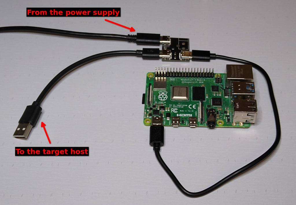
... or Variant #2: Power supply + Y-splitter based on power blocker
- x1 USB-A to USB-C cable (male-male).
- x1 USB splitter.
- x1 USB Power Blocker - Will go into the USB-A end towards the target host.
- x1 Raspberry Pi Official USB-C Power Supply.
... or Variant #3: Power supply + DIY Y-splitter for soldering
- x1 USB-A to USB-C cable (male-male).
- x1 Another cable USB-A to any (male-any).
- x1 Any 5V 3A power supply with USB-A socket.
... or Raspberry Pi Zero 2 W
- x1 USB-A to USB-Micro cable (male-male).
- x1 Raspberry Pi Zero Camera Cable. Not compatible with Auvidea B101.
- x1 Raspberry Pi Official USB-Micro Power Supply.
- *x1 USB-C/Power splitter Module
-
Optional features:
✮ ✮ ✮ ATX controller to manage the target host's power
With this part, you will be able to remotely turn on, turn off and restart your computer!
- x4 optocouplers
TLP241BF(F
or PC817X2NSZ9F (the input polarity must be observed)
or OMRON G3VM-61A1
or OMRON G3VM-61AY1
Don't use random relay modules or random optocouplers! Some of these may not be sensitive enough for the Raspberry Pi, some others may be low-level controlled. Either use relays that are activated by a high logic level, or follow the design provided. See details here. - x4 390 Ohm resistors (see here for alternatives).
- 2x 4.7 kOhm resistors.
- x10+ dupont wires male-male.
- x1 a breadboard.
- various wires for the breadboard.
This can be partially replaced by using Wake-on-LAN in the software, but it will not allow to reboot a hung system, and it is not as reliable as an ATX controller. Sometimes the Wake-on-LAN on the host just stops working, for its own or network reasons.
VGA video capture
If you want to capture VGA from your server instead of HDMI, buy the VGA-to-HDMI converter. Some converters have issues with not supporting all resolutions and refresh rates.
- x4 optocouplers
TLP241BF(F
or PC817X2NSZ9F (the input polarity must be observed)
or OMRON G3VM-61A1
or OMRON G3VM-61AY1
Kit parts suitable for assembly are also on sale in Poland.
Setting up the hardware
-
Video capture device:
✮ ✮ ✮ HDMI-CSI bridge
Insert the flexible flat cable of the HDMI-CSI bridge into the narrow white connector on the Raspberry Pi (the closest one to big USB sockets). It is labeled
CAMERA. To insert you need to open the connector first. On the Raspberry Pi side you can gently lift the black part up and a little bit sideways:Opening the MIPI CSI slot on the Raspberry Pi 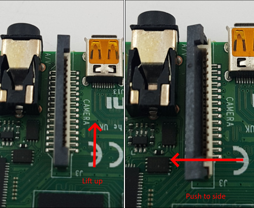
For the HDMI-CSI bridge this operation depends on the version you bought. Either pull it gently up as on the Raspberry or push it sideways. Make sure that the cable is inserted on the correct side and until it stops, and then push the black latch back. Avoid using force when pushing the cable in, as the slots bond to the PCB is quite fragile. Never connect or disconnect the flat cable from a powered device. This is not Plug-and-Play, and you can damage it. Also use only the cable that was included with the device package, or make sure that the third-party cable has the correct pinout.
HDMI-CSI bridge connected to Raspberry Pi 4 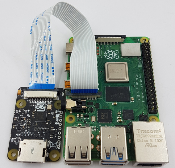
HDMI-CSI bridge connected to Raspberry Pi 2 W (using the adapter cable) 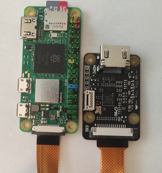
... or HDMI-USB dongle
Connect USB dongle to exactly this port. It is bound in the software so the OS does not confuse the video device with something else.
Raspberry Pi 2 and 3 Raspberry Pi 4 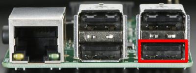
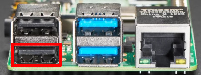
There are many revisions of the Raspberry Pi boards and you may come across one that we haven't tested. If the binding fails, the device will be available for all ports. Everything will work, but if you use a webcam and Linux mistakes it for a dongle, write to us and we will fix it.
-
USB cable and power supply
✮ ✮ ✮ Raspberry Pi 4
✮ ✮ ✮ Variant #1: Power supply + ready-made Y-splitter module
... or Variant #2: Power supply + Y-splitter based on power blocker
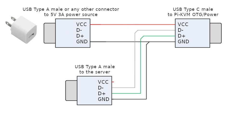
... or Variant #3: Power supply + DIY Y-splitter for soldering
It is assumed that if you have followed this path, you know how to handle a soldering iron and a multimeter.
The Y-splitter can be soldered from two suitable USB cables. Check the attached diagram. The appropriate USB pinout(s) can easily be found on Google.
Please note that if you make a Y-cable from two no-name cables, the colors of the wires may not match those shown. Use a multimeter to make sure the connections are correct.
Video How-To: Making a USB Y-splitter cable
... or Raspberry Pi Zero 2 W
This board has two USB micro connectors: one for power supply (marked as
PWR) and the second for emulating a USB gadget (marked asUSB). Both connectors have a common power line, so to prevent Raspberry power from entering the USB port of the target host, it is required to make a special USB A-to-Micro cable without power line.One way is to physically cut the power wire inside the USB cable.
An easier way is to stick a piece of duct tape, as shown in this picture:
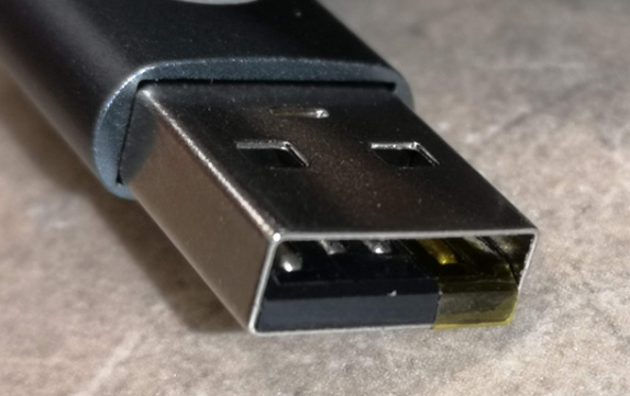
Connect the power supply to the
PWR, and your magic cable to theUSB. The magic cable will be used to connect the device to the target host. -
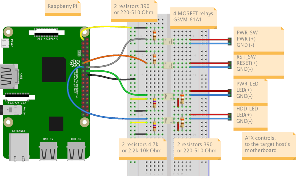
✮ ✮ ✮ Optional feature: ATX controller
Connect all the parts according to this scheme:
Simple wiring diagram
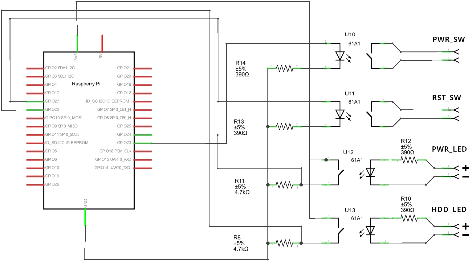
Electrical schematic diagram for advanced users
-
Flash the memory card with PiKVM OS and insert it to Raspberry Pi.
Wiring
Warning
Double check that the circuit is assembled correctly to avoid any damage of the hardware.
PiKVM V2 requires several items available separately:
- Ethernet cable (Raspberry Pi 4 only)
- HDMI cable
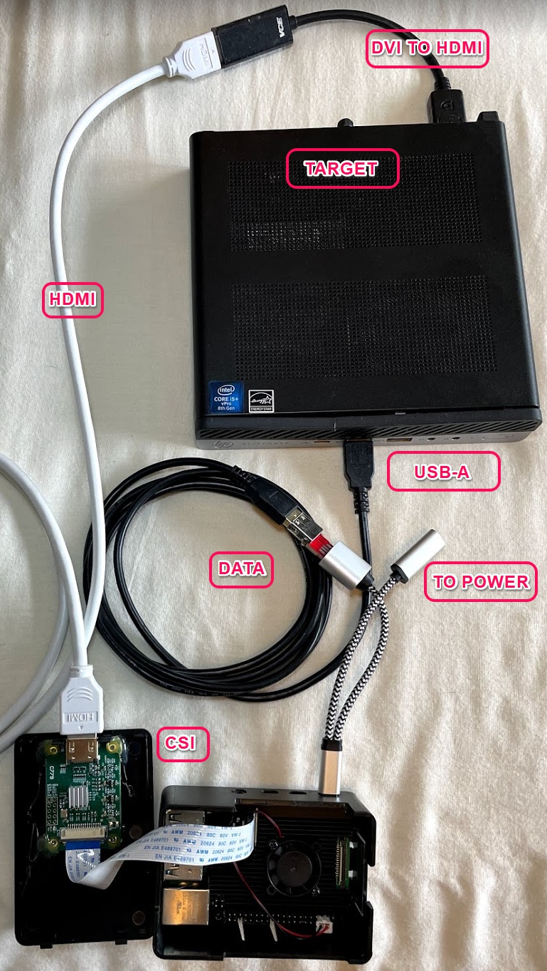
Let's connect all the wires before you power up the device.
-
Connect the HDMI video capture device to the video output port on the target host.
-
Using the Y-cable, connect the Pi's OTG port to the USB on the target host.
-
Raspberry Pi 4: connect Ethernet to the network, e.g., to the WiFI router.
-
Connect the ATX controller if you built it
To control the power, two display LEDs (power and HDD activity) and two buttons (power and reset) are provided on the front panel of the computer case. They are connected by wires to pins on the motherboard.
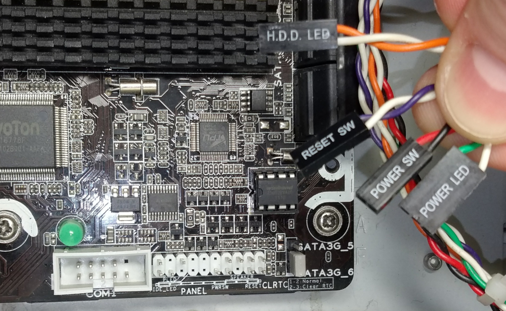
All you have to do is connect the PiKVM ATX controller to their wires by making a parallel connection. Please note that the pinout differs on different motherboards, so before you continue, check the documentation on your motherboard for correct pinout.
The following illustration shows how the connection between the power LED and the power button should be performed:
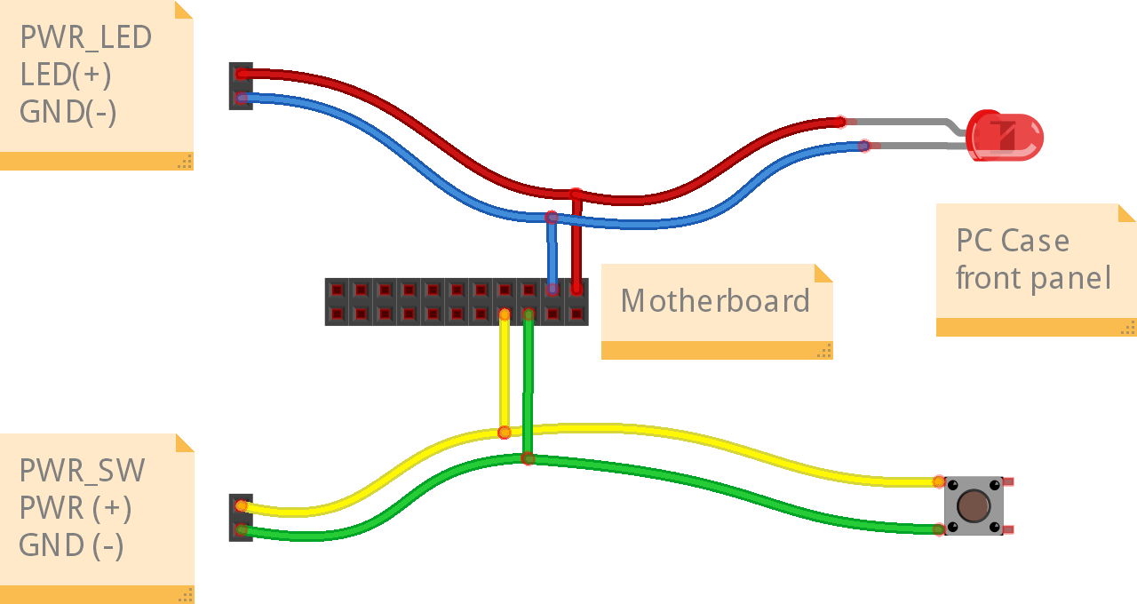
On the left are the wires from the PiKVM ATX controller, the pad in the middle indicates the pins on the motherboard, and on the right are the LED and button of the target host. The implementation of this scheme is left to your discretion and can be performed, for example, by cutting wires and performing twisting, followed by insulation with duct tape.
Be careful and respect the polarity of the LEDs. The polarity of the button does not matter (they have no polarity at all). The connection of HDD LED and reset switch is performed in the same way.
Power up
If everything is assembled correctly, attach the power supply to the Raspberry Pi.
After turning on the power, PiKVM OS generates unique SSH keys and certificates and performs all necessary operations on the memory card. It takes a few minutes.
Do not turn off the device until it's fully booted for the first time.
Configure the display
The operating system on your remote computer will treat PiKVM as an additional display and use it in the Extend mode by default. That's why you will see an empty desktop when you first connect.
To avoid that, go to the display settings in your remote computer's operating system and enable the mirror mode for the external screen that you operating system identifies as PiKVM. Refer to your operating system's documentation on that.
Access PiKVM
You need to know PiKVM's IP address in the network to be able to access it. Unlike V3 and V4, PiKVM V2 doesn't have an OLED to display the IP address it receives automatically. You need to discover it manually. There are several ways to do that.
- Common way: Open the web interface of your router and find the list of issued IP addresses there.
- Linux-only: Use the
arp-scan --localnetcommand. - Linux, MacOS, Windows: Download and run Angry IP Scanner.
- Windows PowerShell: Use the
arp -acommand.
Let's assume that PiKVM has received the address 192.168.0.26 and has also been assigned a hostname pikvm.
Type the URL in the browser's address bar and press Enter: https://192.168.0.26/ or https://pikvm/.
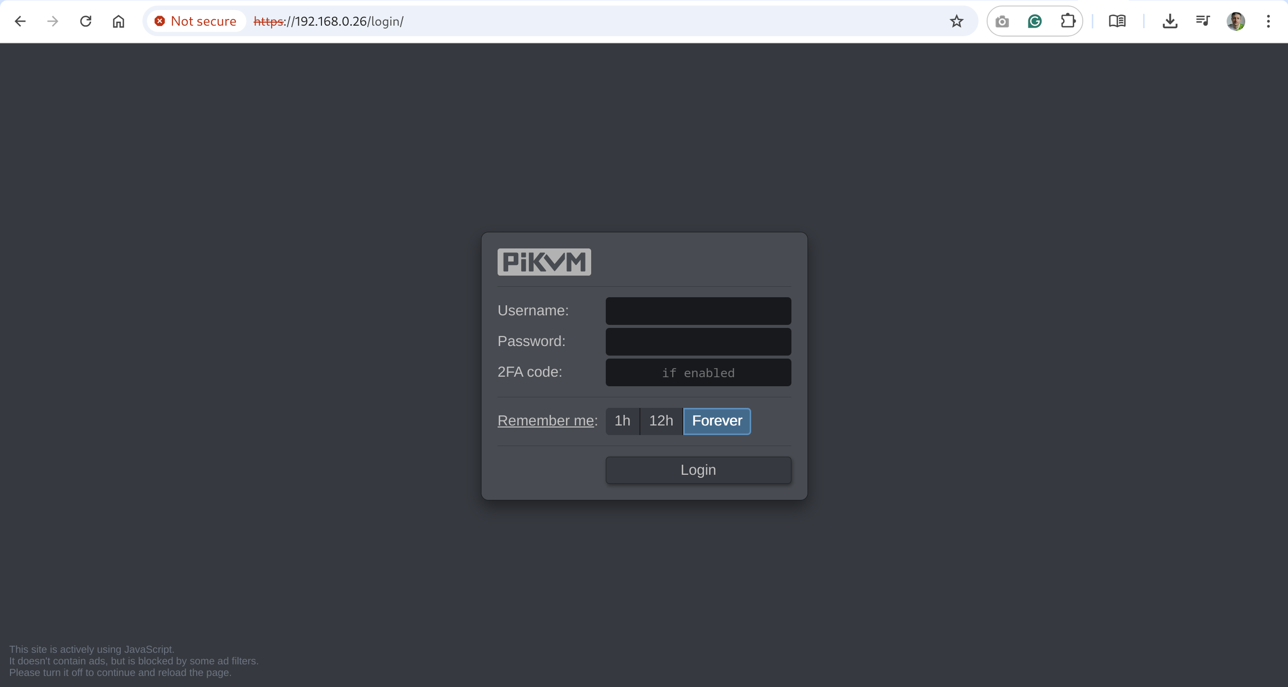
Submit the default credentials and click Login:
- Username:
admin - Password:
admin - 2FA Code: disabled by default, skip this field
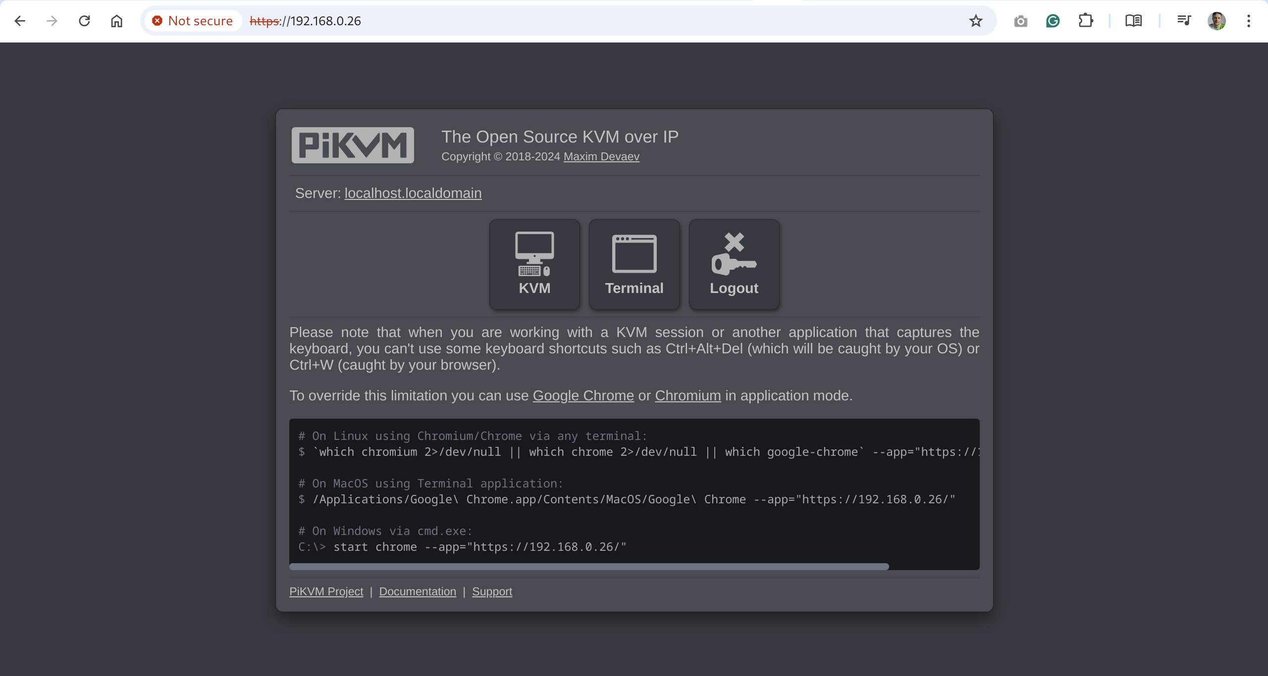
You will see the initial dashboard screen of the PiKVM where you can access the remote host, connect to the PiKVM command line, or log out:
Change the default passwords
For security's sake, it's best to change the default passwords immediately after running PiKVM for the first time.
Passwords are important!
Please ensure that you change both passwords: for Web UI access and for the Linux superuser (root).
To do that:
-
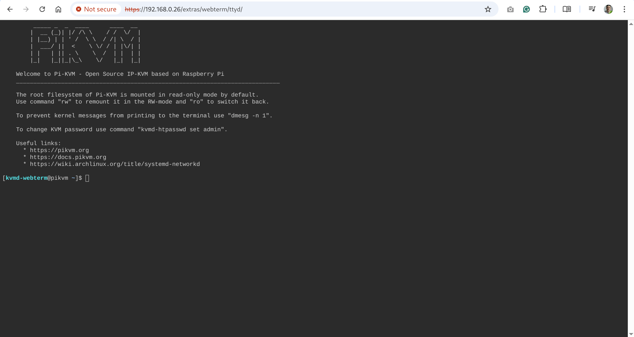
On the initial dashboard screen, click the Terminal button to open the web terminal. You will see this command line interface:
-
Gain Linux superuser privileges:
$ su -When prompted for password, use
root. -
Run
rwto change the access to the SD card to the write mode:[root@pikvm ~]# rw -
Change the password for the Linux superuser:
[root@pikvm ~]# passwd rootSubmit the new password, retype it the second time to confirm, press Enter, and you should see this:
passwd: password updated successfully -
Change the password for web access:
[root@pikvm ~]# kvmd-htpasswd set adminSubmit the new password, retype it the second time to confirm, and press Enter.
-
Run
roto change the access to the SD card back to the read-only mode:[root@pikvm ~]# ro -
Press Ctrl+D or type "exit" and press Enter to drop the root privileges.
-
Go back one page in the browser. You should be back to the initial dashboard screen.
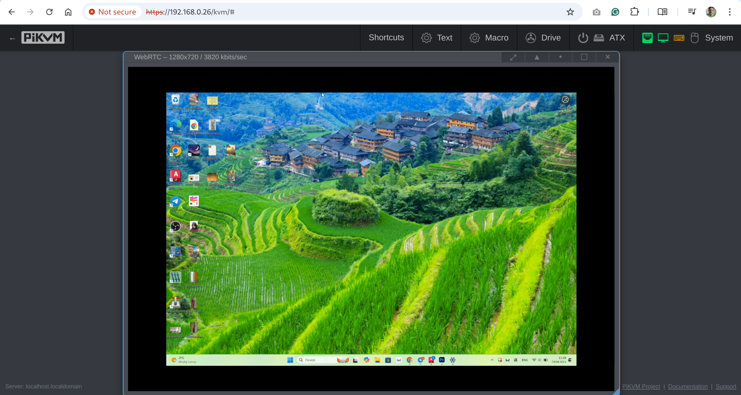
Access the remote system
-
On the initial dashboard screen, click the KVM button to access the remote host.
-
You should now see the host system's display and interact with it remotely using a keyboard and a mouse.
Important next steps
-
We strongly recommend to update the PiKVM OS after the first launch:
Updating PiKVM OS
Tip
We recommend updating PiKVM OS only if you have physical access to the device, or in the most extreme cases. The update process is very reliable, but there is always a small chance that something may go wrong so reflashing will be required. PiKVM cannot be bricked, but you need physical access to the memory card for this operation.
To update, run following commands under the
rootuser:[root@pikvm ~]# pikvm-updateIf you encounter an error like:
[root@pikvm ~]# pikvm-update
bash: pikvm-update: command not found
It's most likely you have an old OS release. You can update the OS as follows:
[root@pikvm ~]# rw
[root@pikvm ~]# pacman -Syy
[root@pikvm ~]# pacman -S pikvm-os-updater
[root@pikvm ~]# pikvm-update
Next time you will be able to use the usual method with
pikvm-update. -
Learn about basics of PiKVM OS Configuration: where to find configs, how to edit the, etc.
Configuring PiKVM OS
Need more info? We have it!
The following is a brief guide to configuring PiKVM. For more information (including the basics of YAML syntax and how to use a text editor in the Linux console), please refer to this page.
Most of the PiKVM configuration files are located in the
/etc/kvmddirectory.The
/usr/lib/kvmd/main.yamlfile defines the platform configuration, and you should never edit it. To redefine system parameters use the file/etc/kvmd/override.yaml. All other files that are also not recommended for editing have read-only permissions.For automated deployment, you can put
.*yamlfiles into/etc/kvmd/override.ddirectory. Theoverride.yamlfile definitions takes precedence over theoverride.ddirectory and it is intended for local manual configuration.A complete list of all parameters can be viewed using the
kvmd -mcommand.A list of your non-default overrides can be viewed using the
kvmd -Mcommand.Files with the
*.yamlsuffix uses the YAML syntax and describes a parameter tree with key-value pairs of different types. To define the parameters within one section, an indent of 4 spaces is used. Comments starts with the#symbol.Only 4 spaces should be used for indentation
Be careful when editing YAML and follow this rule. Invalid indentation or tabs instead of spaces will cause an error when starting the services.
Sections under the same keys should be merged:
-
Wrong:
kvmd: gpio: drivers: ... kvmd: gpio: scheme: ... -
Correct:
kvmd:
    gpio:
        drivers: ...
        scheme: ...
For simple config overrides you don't need to use a text editor, you can do this with
kvmd-overridecommand. For example, enabling the microphone audio on PiKVM V3/V4:[root@pikvm ~]# kvmd-override --set otg/devices/audio/enabled=trueThis puts a config override looks like this:
otg:
    devices:
        audio:
            enabled: true
In the
/etc/kvmd/meta.yamlfile you can specify some information regarding this PiKVM installation in an almost free YAML format. -
-
Get to know PiKVM Web UI: read this help section to better understand all the possibilities of the web user interface.
-
Configure the magic key: define which key to use to start sending shortcuts to the target host system.
-
Tune the HDMI dongle capture device if you're using it:
Persistent HDMI cable connection with USB dongle
Many USB video capture devices tell the server's video card that the HDMI cable is supposedly disconnected. This may lead to the fact that if you boot the server without an active stream, the server will not detect your capture card. This is easy to fix:
-
Switch filesystem to RW-mode:
[root@pikvm ~]# rw -
Edit file
/etc/kvmd/override.yamland add these lines:kvmd: streamer: forever: true cmd_append: [--slowdown] -
Finish:
[root@pikvm ~]# ro [root@pikvm ~]# systemctl restart kvmd -
Check that everything is working.
-
Further recommendations
- Harden the remote access by enabling 2FA.
- Configure access to PiKVM from the Internet using port forwarding or Tailscale VPN.
- Learn how configuration files are structured.
- Read how PiKVM is identified on the target host.
Known issues and limitations
-
Max resolution.
PiKVM V2 with CSI bridge can only handle the maximum resolution 1920x1080@50Hz, 60Hz is not supported due hardware limitation. You can use any other resolution less than the specified one, for example 1280x720@60Hz. If you have any problems with video on CSI bridge, follow this guide. -
Motherboards compatibility.
There may be compatibility issues with some motherboards, such as HP or DELL. If there is no image from the BIOS, you can fine-tune the HDMI settings, but it is possible that the mass storage devices will not be available in the BIOS. In the latter case, USB dynamic configuration will solve the problem.
Basic troubleshooting
-
Ensure that you are using the right OS image for your platform by running the following command:
pacman -Q | grep kvmd-platform. -
If you are not getting a display, run the two following commands:
dmesg | egrep 'tc35|1-1.4|uvc'systemctl status kvmd-tc358743
If you see a failed message on that output, be sure verify the orientation of the CSI cable or try reseating it.
Note that this is not a hotplug device, and you must first turn off the power.
Getting user support
If something doesn't work, check out our FAQ. Otherwise, head straight to our Support.